
What is DPS Switch?
Components of Differential pressure switches
Range – The span of differential pressures or flow rates within which the sensing element of a given switch can be set to actuate an electric switch.
Set or Actuation Point – The exact air pressure or flow rate which will cause the electric switch to actuate.
Rated Pressure – The maximum pressure that the actuating components of the switch in contact with the media can withstand continuously and/or repeatedly without risk of permanent damage.
Maximum Surge Pressure – Safe pressure for the switch housing but which may damage the mechanism by the continuous or repetitive application.
Normally Open Switch – A Switch in which the contacts are normally open. Actuation closes the contacts.
Normally Closed Switch – A switch in which the contacts are normally closed. Actuation opens the contacts.
Single Pole Double Throw (SPDT) Switch – A switch combining both normally open and normally closed switch contacts.
Null Switch – A floating contact switch with a zone of no contact. Often used to operate reversible motors.
Repetitive Accuracy – The ability of a pressure or flow switch to operate repetitively at its set point under consistent conditions.
Read more info here
How differential pressure switch works for fans
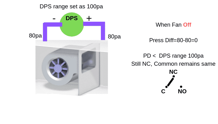
DPS is installed across fans in order to identify actual fan running condition by the pressure difference so, DPS positive tube must be installed after the fan or say positive side and negative tube to be installed before the fan or open to the environment or say negative side and pressure range selected as 100 pa for DPS.
1. Initially when a fan at off condition, before the fan and after fan will be same pressure, so there is no differential pressure across before and after the fan.here pressure differential pressure or PD is zero.
PD=0pa and lesser than 100pa(range)
so here still NC and C remain the same.
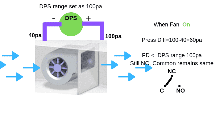
2. When the fan starts to run, let us say on the negative side is 40pa and the positive side is 100pa, where the Pressure difference across the fan of the positive and negative side is
PD=100-40pa.
PD=60pa still lesser than 100pa(range).
so here still NC and C remain the same.
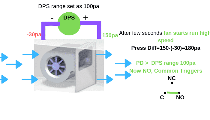
3. Immediately when the fan runs at high speed, let say pressure difference before the fan and after fan will be high let say 150pa in positive side and -30pa in the negative side so
PD=150pa-(-30pa)
PD=180pa which is greater than 100pa(range).
so here DPS triggers NC to NO and C.
This signal will be connected to BMS controllers or any other control circuit to perform the required operation.
Note
However fan running condition can be monitored from relay contact of the motor control circuit panel, but here DPS is used to know the actual fan running condition by confirming flow across the fan because from the motor panel will trigger the relay but not know whether fan really running or not, sometimes motor belt damage.
How differential pressure switch works for filter
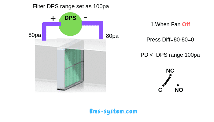


DPS is installed across the filter in order to identify filter dirty condition by the pressure difference so, DPS positive tube must be installed before the filter or say positive side(when dirty particles get into the filter, pressure will increase here) and negative tube to be installed after the filter say negative side and pressure range selected as 100 pa for DPS.
1. Initially when a fan at the off condition, before the filter and after filter will be same pressure, so there is no differential pressure across before and after the filter. here pressure differential pressure or PD is zero.
PD=0pa and lesser than 100pa(range)
so here still NC and C remain the same.
2. When the fan starts to run, let us say on the negative side is 100pa and the positive side is 105pa, where the Pressure difference across the fan of the positive and negative side is
PD=105-100pa.
PD=5pa still lesser than 100pa(range).
so here still NC and C remain the same.
3. Immediately when the dirty particles get into the AHU duct and it’s filtered by the filter, let say pressure difference before the filter and after the filter will be little high let say 180pa in positive side and 90pa in the negative side so
PD=180pa-90pa
PD=90pa still lesser than 100pa(range).
so here still NC and C remain same or say the filter is still clean and reporting to the BMS
This signal will be connected to BMS controllers or any other control circuit to perform the required operation.
4. After AHU running a long time, when more dirty particles get into the AHU duct and it’s filtered by the filter, let say pressure difference before the filter and after the filter will be high let say 220pa in positive side and 90pa in the negative side so
PD=220pa-90pa
PD=130pa is greater than 100pa(range).
So here DPS triggers NC to NO and C.
This signal will be connected to BMS controllers and report as dirty signal for filter or any other control circuit to perform the required operation.
Please leave a comment if you have any doubts
Thanks a lot Mr. Hamza for explaining the working in the best way. This really helped me to clear all my doubts on DPS. Looking forward for your next topic.
Thank you dear.
can you please provide us your Whatsapp No.
Welcome dear.
Excellent explanation and Work Mr.Hamza.
Thank you Narayanan
Sir excellent explanation.
I need to know about diff pressure sensor which are installed on supply duct.
Why we installed these sensors
Some AHU have 1 pressure sensor and some have 2
One is discharge pressure and other is static pressure would you please help me to understand this topic thanks and Regards
Suleman
Thanks mohamed suleman
Normally pressure sensors installed on the supply duct where AHU has variable air volume (VAV);
When VAV dampers in each room closed to minimum position in order to attain set temperature,
AHU duct presssure increaeses which sensed by pressure sensor and its signal connected bms control the control the speed of AHU Fan speed by VFD.
2 sensors installed in order to get actual pressures in whole duct by taking avergae values of 2 sensors .
One will be installed in after the fans over the striaght duct and second sensors installed on 2/3rd of duct
GOOD MORNING SIR ,
PACKAGE UNIT NEED DPS OR NOT ?
Thank you
Its Based on the requirement if they want to monitor Fan or filter status
Thank you so much bro.. Really helpful..
Aap ka contact no. ya email id mil skti h bhai ??
Hi Hamza. If you have a differential pressure switch across a fan, how do you use this switch to know if the fan is running or not? Say maybe the fan belt breaks, how can the switch be used to determine the flow situation of the fan?
How differential pressure switch works for fans

Prev
1of3
Next
DPS is installed across fans in order to identify actual fan running condition by the pressure difference so, DPS positive tube must be installed after the fan or say positive side and negative tube to be installed before the fan or open to the environment or say negative side and pressure range selected as 100 pa for DPS.
1. Initially when a fan at off condition, before the fan and after fan will be same pressure, so there is no differential pressure across before and after the fan.here pressure differential pressure or PD is zero.
PD=0pa and lesser than 100pa(range)
so here still NC and C remain the same.
2. When the fan starts to run, let us say on the negative side is 40pa and the positive side is 100pa, where the Pressure difference across the fan of the positive and negative side is
PD=100-40pa.
PD=60pa still lesser than 100pa(range).
so here still NC and C remain the same.
3. Immediately when the fan runs at high speed, let say pressure difference before the fan and after fan will be high let say 150pa in positive side and -30pa in the negative side so
PD=150pa-(-30pa)
PD=180pa which is greater than 100pa(range).
so here DPS triggers NC to NO and C.
This signal will be connected to BMS controllers or any other control circuit to perform the required operation.
Hi Hamza
How do you select the pressure range? for example if the AHU has a total static of 550 pa (ESP + ISP), what should be pressure range set point for the DPS?
Thank You
Hi all, you may take a look at our good type 604 Differential pressure switch. These are 100% made in Switzerland.
https://www.linkedin.com/feed/update/urn:li:activity:6703467650355486720
https://www.hubacontrol.com/en/products/mechanical-pressure-switch/mechanical-pressure-switch-604
Good luck and all the best!
Eric,
hi Hamza,
i have two filters connected next to each other, a G4 filter and then a bag filter. how can i use only one DPS effectively, to measure the differential pressure across the two filters?
Good explanation. I am little confuse during the filter on/ off side. I clearly understand the topic.
Good explanation. I am little confuse during the filter on/ off side. I clearly understand the topic.
AHU have two filte 1st after inlet damper 2nd before cooling coil. can you explain which filter is primary and secondary
Dear Mr.Hamza,
The way you explained the system is excellent and informative.If we need to measure the Room pressure with respect to outside pressure, through a wall mount pressure differential indicator transmitter.How will be the arrangement.cab you please advice
If fire dampers are closed either downstream or upstream of the fan (no flow path), will the fan DPS still make?
Practically DPS should not make any contact if there is no flow in the duct.
But incase if fan runs while damper closed and if pressure different is identified..DPS sense and close contact